Series and parallel Connections
When several devices are connected end to end in such a way that there is only one path for the current to flow and so, the same current flows through each, then such a circuit is called a "series circuit". When several devices are connected to a common voltage in a certain manner that they provide alternative paths for the current. Where the current in each path (device) will depend on its resistance. Such a circuit is called “parallel circuit”.Resistances in Series
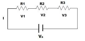
When three resistors, R1, R2 and R3 are connected end to end as shown in the figure below, then it would be referred as resistances in series. In case of series connection, the equivalent resistance of the combination, is sum of these three electrical resistances.Total voltage applied across the combination of resistances in series, is V. Let the current in the circuit is I. So this current I will pass through the resistance R1, R2 and R3. Applying Ohm’s law , it can be found that voltage drops across the resistances will be V1 = IR1, V2 = IR2 and V3 = IR3.
From figure, the total voltage is the sum of voltage drop across R1, R2 and R3, is V1, V2 and V3 respectively,
then V = V1 + V2 + V3
\ V = IR1+ IR2 + IR3
or V = I (R1 + R2 + R3)
Now, if we consider the total combination of resistances as a single resistor of electric resistance value R, then according to Ohm’s law ,
V = IR
\ IR = II (R1 + R2 + R3)
finally, R = R1 + R2 + R3
So the above proof shows that equivalent resistance of a combination of resistances in series is equal to the sum of individual resistance. If there were n number of resistances instead of three resistances, the equivalent resistance will be
R = R1 + R2 + R3 + ………………..+Rn
Resistances in Parallel
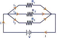
Let’s three resistors of resistance value R1, R2 and R3 are connected in such a manner, that right side terminal of each resistor are connected together as shown in the figure below, and also left side terminal of each resistor are also connected together. This combination is called resistances in parallel.If a voltage, V is applied across this combination, then it will draw a current I. As this current will get three parallel paths through these three electrical resistances, the electric current will be divided into three parts. Say currents I1, I1 and I1 pass through resistor R1, R2 and R3 respectively. The total source current will be sum f branch currents,
I = I1 + I2 + I3
Now, as from the figure it is clear that, each of the resistances in parallel, is connected across the same voltage source, the voltage drops across each resistor is same as source voltage V.
Hence, I1 = V/R1, I2 = V/R2 and I3 = V/R3,
and I = V ⁄ R
where R is the equivalent resistance of the combination.
\ V ⁄ R = V/R1 + V/R2 + V/R3
1 ⁄ R = 1/R1 + 1/R2 + 1/R3
The above expression represents equivalent resistance of resistor in parallel. If there were n number of resistances connected in parallel, instead of three resistances, the expression of equivalent resistance would be
1/R = 1/R1 + 1/R2 + 1/R3 + .......... + 1/Rn
Problem Solving
Example 1 : Three resistors of 5.8W, 10.7 W and 6.5W are connected in series across a 127 V supply. What isa. the total resistance of the circuit
b. the total current in the circuit, and
c. the voltage across each resistor?Example 2 : Find the effective resistance of 20 W, 30W and 6W resistances connected in parallel.
Example 3 : In the circuit as shown in Figure R1 = 40 W, R2=120W, R3 = 80W. If the supply voltage V is equal to 220V then find out;
a. The total resistance
b. The total current
c. The current in each resistance and
d. Voltage across each resistance.


No comments:
Post a Comment